What Is a Prototype Board and How Does It Work?

Time:2026-10-10 Author:Charlotte
0%

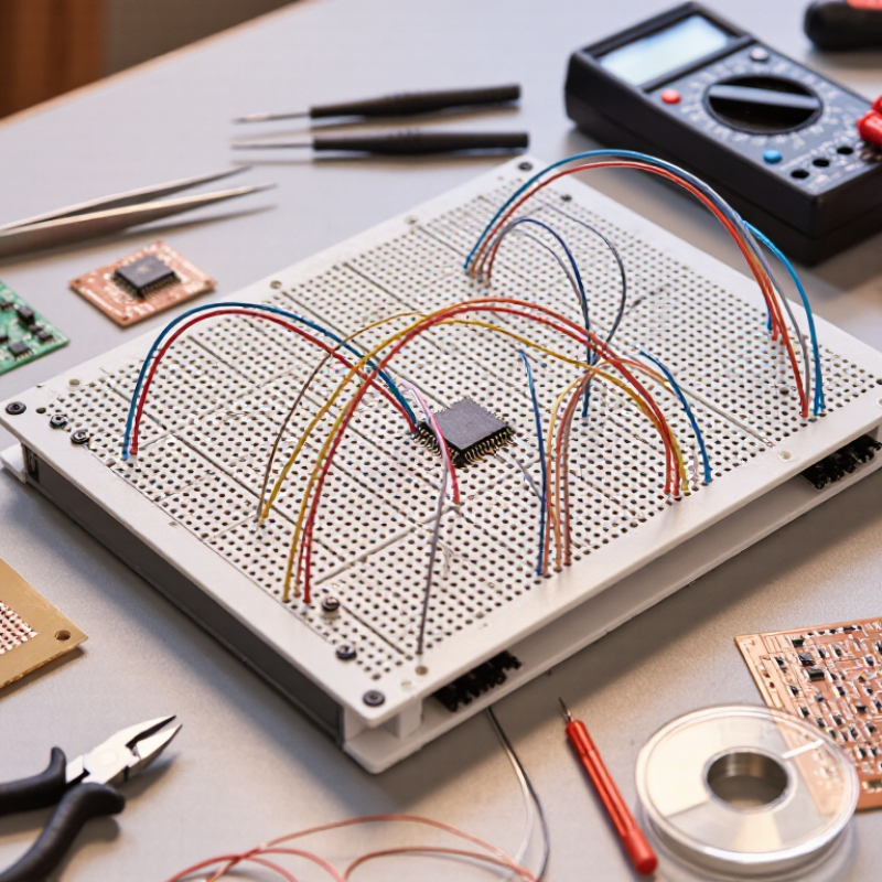
A Prototype Board is a practical surface for building and testing electronic circuits before producing a finished device. It helps engineers, students, and hobbyists connect components, inspect results, and revise designs with less waste. Depending on its type, the board may use temporary contacts, copper pads, or soldered connections. A solderless breadboard allows quick changes, while a perforated board offers stronger, more permanent assembly. Both support the same goal: turning a circuit idea into something visible and testable.

The working principle is simple. Components such as resistors, LEDs, sensors, and integrated circuits connect through conductive paths. These paths carry power and signals between selected points. On a breadboard, hidden metal clips join holes in short rows. On a perfboard, wires or solder create those connections manually. I have found that labeling power rails and checking polarity early prevents many avoidable mistakes. Small details matter. A loose jumper can make a working circuit appear faulty. A reversed LED can stay dark.

A reliable prototype process includes planning, careful wiring, voltage checks, and repeated testing. Measuring with a multimeter is more dependable than trusting a visual inspection. Still, a prototype is not automatically safe or production-ready. It may contain fragile connections, poor heat management, or unexpected electrical noise. That limitation deserves attention. Some early designs also look untidy, and that is normal. The important question is whether the board clearly demonstrates the circuit’s behavior and reveals what needs improvement. This article explains the main types of Prototype Board, how their internal connections work, and when each option is most suitable.
What Is a Prototype Board and How Does It Work?

What a Prototype Board Is and What It Is Designed to Do

What Is a Prototype Board and How Does It Work?

What a Prototype Board Is and What It Is Designed to Do

A prototype board is a temporary platform for testing an electronic circuit before production. It may use spring contacts, jumper wires, and power rails. Another version uses a perforated board with copper pads and soldered components. Both designs make circuit changes easier than redesigning a finished PCB.

The board is designed to prove an idea. Engineers can check voltage, signal behavior, component placement, and basic safety. On a solderless board, internal metal clips connect selected holes in short rows. Power rails distribute positive and negative voltage. On a perforated board, solder creates more permanent electrical paths. Small changes remain possible.

This process matters as electronics production expands. Grand View Research estimated the global printed circuit board market at about 89.7 billion dollars in 2023. It also projected a 5.6% compound annual growth rate from 2024 to 2030. These figures suggest why early circuit validation can reduce expensive redesigns.

A prototype board is not a finished product. It may produce unstable signals at high frequencies. Loose wires can imitate component failures. That detail is easy to miss. Practical testing should include a multimeter, careful labeling, and repeated measurements. A circuit that works once may still need better grounding, shorter connections, or a stronger mechanical layout. Industry reports provide useful market context, but bench evidence must decide whether the design is truly reliable.

What Is a Prototype Board and How Does It Work?

A prototype board provides temporary or semi-permanent connections for testing electronic circuits. This chart shows an example 0–5 V digital square-wave signal measured over 10 milliseconds while a circuit is being evaluated on a prototype board.

The signal alternates between approximately 0 V and 5 V every 1 millisecond, producing a 500 Hz waveform. Engineers can use a prototype board to connect components, observe voltage changes, and modify the circuit before creating a permanent circuit board.

The Main Parts and Connections Found on a Prototype Board

What Is a Prototype Board and How Does It Work?

The Main Parts and Connections Found on a Prototype Board

A prototype board lets you test electronic circuits without soldering permanent connections. Its main surface contains a grid of small holes called tie points. Underneath, metal clips connect selected holes into short electrical groups. On many boards, five holes in one column share a connection, while the center gap separates the two sides.

Power rails usually run along the outer edges. They distribute positive voltage and ground across the board. Some rails are split in the middle, so power does not travel across the entire length. This detail often causes unexpected failures. Check the rail continuity before connecting a circuit.

Jumper wires link components between separate connection groups. Integrated circuits commonly sit across the center gap, allowing their pins to reach different rows. Resistors, capacitors, switches, and sensors can then connect through nearby tie points. In practical testing, keep wires short and use consistent colors for power and ground. It makes faults easier to trace. It also makes the circuit easier to explain.

A prototype board has limits. Loose clips may create unstable readings, especially with delicate sensors or fast signals. Excess current can heat contacts and damage components. Use a multimeter to verify voltage and continuity before applying power. I sometimes expect a circuit to fail because of a component, but the real problem is often one misplaced wire. That is a useful reminder: the board simplifies experiments, but it does not replace careful checking.

How Electrical Signals Move Through a Prototype Board

A prototype board gives electrical signals a temporary path between components. In a solderless board, metal spring clips connect groups of holes beneath the plastic surface. Most five-hole rows share one conductive node, while the center gap separates the two sides. Power rails usually run along the edges, but some rails are interrupted halfway. That small break can quietly stop a circuit.

When a source applies voltage, electrons respond through the connected metal path. A signal travels from the source, through wires and components, then returns through ground. A resistor limits current. A capacitor stores charge and changes the signal’s timing. An oscilloscope probe can reveal the result: a clean square wave may become rounded, delayed, or noisy. Long jumper wires add resistance, capacitance, and inductance. Loose contacts add uncertainty.

This matters more as speed increases. The IPC 2023 International Technology Roadmap discusses 112 Gb/s and 224 Gb/s serial interconnect targets. A solderless prototype board is not designed for those conditions. Even modest digital circuits can show ringing when wires become long. Keep connections short. Place decoupling capacitors close to power pins. Check continuity instead of trusting the hole layout. I have found that many “software” faults begin as one misplaced jumper. The board is convenient, but its hidden parasitics are easy to underestimate. Signal behavior also depends on probe position, grounding, and the quality of each contact. That makes every measurement partly a test of the board itself.

How to Build and Test a Circuit Step by Step

A prototype board is a temporary workspace for building and testing electronic circuits.

A solderless board connects holes through hidden metal strips, allowing components to move without soldering. Place the integrated circuit across the center gap. Insert resistors, sensors, and jumper wires into matching rows. Connect the power and ground rails carefully. Keep power off during assembly. IPC’s 2024 Electronics Industry Demand Forecast projected approximately 5% growth in global electronics manufacturing output for 2024, increasing pressure to test designs quickly and reduce expensive rework.

Build the circuit in small sections. Start with the power connection, then add one component at a time. Check each connection against the schematic. Use a multimeter to measure voltage before adding sensitive parts. A reading near zero can reveal a short circuit. Apply power through a current-limited supply. Observe heat, smell, and unstable readings. Stop immediately if anything seems abnormal. The U.S. Bureau of Labor Statistics projects 5% employment growth for electrical and electronics engineers from 2022 to 2032, showing continued demand for practical testing skills.

My early prototypes often failed because I trusted wire colors instead of measurements. That was careless. I now label every rail and record each reading. Test the input first, then verify the output under a small load. Change only one variable between tests. Otherwise, the cause becomes unclear. Breadboards also introduce loose connections and stray capacitance, so a working prototype may still need a soldered version. My process is better now, but not perfect.

Common Uses, Advantages, and Limitations of Prototype Boards

A prototype board provides a temporary platform for testing electronic circuits before committing to a permanent design. In a solderless version, connected holes share internal metal strips. Jumper wires and component leads complete the circuit. A solderable board uses copper pads instead, creating stronger connections for longer tests. On a workbench, I usually begin with a simple power check, then measure each rail with a multimeter.

Its main advantage is speed. Components can be moved without redesigning a circuit board. This makes it useful for sensor experiments, control logic, educational projects, and early product development. A clear layout also helps engineers trace signals and locate wiring mistakes. It is inexpensive and reusable. That matters during repeated trials. Small changes become practical, not expensive.

Limitations appear as circuits become faster, hotter, or more powerful. Loose jumper wires can cause intermittent faults. Internal contacts also add resistance and unwanted capacitance. These effects may distort timing signals or produce unstable readings. A prototype board is usually unsuitable for high-current loads, high-frequency communication, or vibration-heavy equipment. I have sometimes blamed a software error when the real problem was a weak connection. That assumption is not always right. Careful probing, shorter wires, and written test notes improve reliability, although they cannot replace a properly designed circuit board.

What Is a Prototype Board and How Does It Work? - Common Uses, Advantages, and Limitations of Prototype Boards
Prototype Board Type How It Works Typical Uses Typical Pitch and Current Range Reusability Main Advantages Main Limitations
Solderless Breadboard Spring contacts under the holes connect groups of five holes electrically. A central gap separates the two sides of a standard dual-inline integrated-circuit area, while side rails commonly distribute power. Temporary testing of sensors, microcontrollers, logic circuits, LED circuits, and basic analog circuits. Common hole pitch: 2.54 mm (0.1 in). Suitable for low-voltage, low-current circuits; practical current is commonly kept around 0.5–1 A per contact group, depending on the board and connection quality. High Fast assembly, no soldering, easy component changes, and low setup cost. Loose contacts, parasitic capacitance, voltage drop, and noise make it unsuitable for high-frequency, high-current, or vibration-prone applications.
Perfboard Individual plated or unplated holes are arranged on a rigid insulating board. Components are inserted and connected with soldered wires, component leads, or short jumpers. Small analog circuits, simple digital circuits, low-volume prototypes, and semi-permanent hobby or laboratory builds. Common hole pitch: 2.54 mm (0.1 in). Current capacity depends mainly on wire size, solder joints, and any added copper traces. Low to Medium More mechanically stable than a solderless breadboard and relatively easy to customize. Wiring can become difficult to troubleshoot, circuit changes require desoldering, and there is no automatically defined circuit routing.
Stripboard Parallel copper strips connect adjacent holes in rows. The strips can be interrupted with a cutting tool to create separate electrical sections. Compact through-hole circuits, control circuits, power-management prototypes, and repeatable one-off assemblies. Common hole pitch: 2.54 mm (0.1 in). Current is limited by copper-strip width, trace length, temperature rise, and solder-joint quality. Low to Medium Provides a predictable copper layout, reduces point-to-point wiring, and offers better mechanical strength than a breadboard. Routing is constrained by the fixed strip pattern; incorrect cuts are difficult to repair, and dense layouts may be hard to modify.
Prototype PCB A custom printed circuit board uses etched or deposited copper traces, drilled or laser-formed holes, and solder pads to create a defined interconnection pattern. Functional validation, embedded systems, power circuits, signal-integrity testing, and designs approaching production. Common through-hole or surface-mount pitches range from about 0.5 mm to 2.54 mm. Trace current depends on copper thickness, trace width, allowable temperature rise, and board design. Low Compact, repeatable, electrically consistent, mechanically robust, and suitable for controlled impedance or multilayer routing. Requires design files and fabrication time; revisions are less convenient, and manufacturing errors can make changes costly.
Wire-Wrap Board Insulated wires are wrapped tightly around square terminal posts to form gas-tight electrical connections without soldering. Digital logic experiments, educational systems, backplanes, and circuits requiring frequent point-to-point reconfiguration. Common terminal spacing: 2.54 mm (0.1 in). Best suited to low-voltage, low-to-moderate-current digital or control circuits. High Connections can be changed without heating components, and each wire can be traced or replaced individually. Labor-intensive, physically bulky, less suitable for high-speed signals, and dependent on correct wire length and wrapping technique.

FAQS

What is a prototype board used for?

It provides a temporary platform for testing electronic circuits. Components can be moved without redesigning a circuit board.

How are holes connected on a solderless board?

Most five-hole rows share one internal metal node. A center gap separates the two sides.

Why can a power rail fail unexpectedly?

Some power rails stop halfway along the board. A hidden break can quietly interrupt the circuit.

How does a signal move through the circuit?

It travels from the voltage source through wires and components. Then it returns through the ground connection.

What do resistors and capacitors do?

A resistor limits current. A capacitor stores charge and changes signal timing.

Why might an oscilloscope show a distorted signal?

Long jumper wires add resistance, capacitance, and inductance. A clean square wave may become rounded, delayed, or noisy.

Are prototype boards suitable for fast or powerful circuits?

Usually not. They can struggle with high-speed signals, high-current loads, heat, and vibration.

How can testing become more reliable?

Keep wires short and place decoupling capacitors near power pins. Check continuity with a multimeter instead of trusting hole positions.

Can a prototype board cause software-like faults?

Yes, sometimes. A misplaced jumper or loose contact may look like a programming error.

What should users remember about measurements?

Probe position and grounding affect the result. Every measurement partly tests the board itself. Mistakes still happen.

Conclusion

A Prototype Board is a reusable platform for designing, assembling, and evaluating electronic circuits without permanently soldering components together. It is typically made with a grid of holes connected by hidden conductive strips, allowing components, jumper wires, power sources, and signal devices to be arranged quickly. Understanding the board’s power rails, terminal strips, connection points, and separation gaps is essential because each group of linked holes shares an electrical path, while different groups remain isolated.

To build a circuit, begin by planning the connections, placing the components, and linking them with wires according to the circuit design. Apply power only after checking polarity, continuity, and possible short circuits, then use suitable measuring tools to observe voltage and signal behavior. Prototype boards are useful for learning, testing ideas, troubleshooting, and making design changes efficiently. However, they may produce loose connections, unwanted electrical effects, and limited performance at high speeds or with large currents, so a completed design may eventually require a more permanent circuit structure.


Charlotte

Charlotte

Charlotte is a seasoned marketing professional with a deep understanding of the company's portfolio and a passion for elevating its presence in the market. With a keen eye for detail and a commitment to excellence, she ensures that our professional blog is regularly updated with insightful articles......