Choosing the right Single Sided Pcb begins with understanding where simplicity creates value. A single copper layer can reduce material use, shorten production steps, and make inspection easier. It can also limit routing freedom. That trade-off matters for global buyers managing price, lead time, and supply consistency. Bob Willis, a respected PCB assembly specialist, offers a useful manufacturing principle: “A board should be designed for the process that will build it.” The wording is simple. The lesson is not.
This guide examines the top 10 Single Sided Pcb types used across practical industries. Examples include power-control boards, LED lighting panels, appliance circuits, toys, calculators, and basic industrial interfaces. Some use paper phenolic substrates for economical, high-volume products. Others use FR-4 for stronger mechanical performance and better thermal stability. Copper thickness, surface finish, hole design, and solderability can change the final result significantly. A cheap board is not always a cost-effective board.
Real factories reveal the details. A narrow trace may look acceptable on a drawing but fail during repeated thermal cycling. A poorly supported connector can lift its pad after frequent plugging. These issues are easy to underestimate. Even experienced teams miss them sometimes. Buyers should request sample approvals, material specifications, electrical tests, and production references before placing large orders. Standards and supplier capability should guide decisions, not attractive pricing alone. This overview is practical, but not perfect; application conditions differ, and one ranking cannot fit every market.
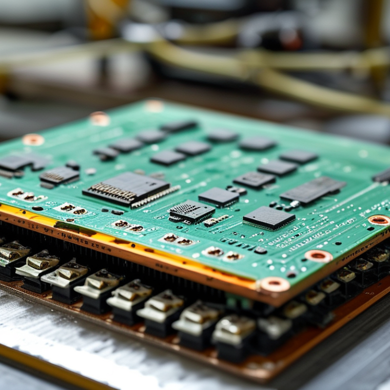
Top 10 Single Sided PCB Types for Global Buyers
Single Sided PCB Basics and Core Construction Features
A single-sided PCB carries copper traces on one surface only. The reverse side usually supports components, labels, or mechanical mounting. Its core includes a substrate, copper foil, solder mask, and silkscreen. Common substrates include FR-4, paper phenolic, and aluminum-backed laminates. Each choice changes cost, heat transfer, drilling behavior, and service life. Keep it simple. For low-frequency controls, LED modules, timers, and household interfaces, this structure often provides enough electrical performance.
IPC-2221 describes design principles for printed boards, while IPC-6011 defines general performance expectations. These references guide trace spacing, conductor sizing, and material selection. Grand View Research estimated the global PCB market above US$76 billion in 2023. That figure covers all PCB categories, not single-sided boards alone. Still, it shows why consistent construction data matters to international buyers. A 1.6 mm board thickness, 35 μm copper, and standard solder mask are common starting points. However, suppliers may interpret tolerances differently.
Thermal design deserves close attention. Aluminum-backed boards can move heat away from high-power LEDs more effectively than paper-based materials. Yet they may increase machining cost and limit certain drilling options. Designers should verify dielectric strength, surface finish, flammability rating, and operating temperature. UL 94 V-0 is widely requested, but certification claims need supporting documents. I have seen otherwise acceptable prototypes fail after humidity testing. The weak point was not the circuit. It was inadequate edge sealing and unverified material data.
Single-sided PCBs remain practical when the circuit is simple, cost-sensitive, and easy to inspect. Classification is not perfectly universal, but ten major types appear frequently in global sourcing.
The first type is paper-phenolic board, designed for low-cost household controls. FR-4 single-sided board offers better heat resistance and mechanical strength. Aluminum-backed board moves heat away from LED circuits. Flexible polyester board supports thin displays and simple membrane controls. Flexible polyimide board survives repeated bending and tighter installation spaces. RF single-sided board uses controlled materials for antenna and sensor circuits. Carbon-ink board adds durable, low-current switch contacts. Power-supply board uses wider copper paths and larger safety clearances. High-voltage control board increases creepage distance around exposed conductors. Finally, plated single-sided board improves hole strength and assembly reliability. A 2024 Prismark market report placed automotive and computing among major PCB demand sectors. That shift favors thermal and mechanically stable designs. IPC’s 2023 PCB Technology Roadmap also highlights thermal management and material selection as continuing engineering concerns.
Tips: Confirm copper thickness, board thickness, operating temperature, and creepage distance before requesting quotations. Ask for dielectric data, not only the material name. Check whether solder-mask color affects inspection. It usually does less than buyers expect. One overlooked issue is connector stress. Add support holes or stiffeners when cables move during service. Also, single-sided routing can require jumpers. That may reduce the expected cost advantage.
Ten major single-sided PCB types explained by substrate design, thermal behavior, and typical function.
The chart compares representative substrate thermal conductivity values in W/m·K. Higher values generally support better heat spreading in LED, power, and high-temperature applications. The figures are typical engineering values rather than market-share data; actual performance depends on the dielectric layer, copper thickness, board construction, and operating conditions.
Paper phenolic and CEM-1 boards are commonly selected for economical controls and consumer products. Standard and high-Tg FR-4 are used for general-purpose rigid circuits. Aluminum and copper metal-core boards are suitable for thermal management, while polyimide flex and PTFE laminates serve flexible and high-frequency designs. Alumina and aluminum nitride ceramic boards are used where electrical insulation and strong thermal performance are required.
Single-sided PCBs suit products with clear signal paths and controlled costs. Paper phenolic boards work well in remote controls, toys, and simple timers. Their low price supports high-volume devices, but moisture can reduce stability.
Standard FR-4 boards handle control panels, small appliances, and sensor modules. They provide stronger insulation and better heat resistance. Bare-copper versions fit low-stress circuits and basic prototypes. Plated-hole versions support more reliable component mounting. This detail matters during vibration.
Aluminum-backed boards move heat from LED lamps and compact power supplies. Thick-copper variants support battery chargers, relays, and low-voltage motor controls. Flexible polyimide boards fit hinged displays, wearable sensors, and narrow lighting assemblies.
High-temperature materials serve heating controls and engine-area instruments. Ceramic-filled options suit demanding thermal environments, though their brittleness needs careful handling. Silver-finished surfaces can improve solderability in fine-pitch assembly. Tin finishes remain practical for general production.
RF-focused layouts can serve simple antennas and wireless sensor nodes, but single-layer routing limits grounding. That limitation is easy to underestimate.
Buyers should check current load, bend radius, humidity, and operating temperature before selecting a variant. A cheaper board is not always the reliable choice.
For global buyers, single-sided PCB selection starts with the working environment, not the lowest quotation. Grand View Research valued the global PCB market at approximately USD 89.7 billion in 2023. Its report projects a 5.6% compound annual growth rate through 2030. That growth increases material variation and supplier differences.
Paper-phenolic boards suit low-cost controls and simple household products. CEM-1 improves dimensional stability with limited cost growth. FR-4 offers better heat resistance and mechanical strength, while aluminum-backed boards manage heat near LEDs or power components. Flexible single-sided circuits reduce weight and fit narrow assemblies. Check copper thickness, dielectric thickness, glass-transition temperature, and coefficient of thermal expansion. A 35-micrometre copper layer may work for signal traces, but high-current paths often need more copper.
Performance claims need physical evidence. Ask for laminate certificates, solderability records, and cross-section samples. IPC-6011 covers performance requirements, while IPC-A-600 defines visible acceptance criteria for finished boards. Inspect edge quality, drilled holes, exposed copper, and solder-mask coverage. A board can look clean and still contain weak adhesion. That is easy to miss. I would also compare thermal cycling data, not only room-temperature test results. My own caution is simple: a cheaper material may pass inspection today, then warp during soldering or fail after repeated heating. A small pilot order reveals more than a polished datasheet.
| Rank | Single-Sided PCB Type | Typical Base Material | Typical Copper Thickness | Typical Dielectric or Board Thickness | Thermal Characteristics | Electrical and Mechanical Performance | Common Global Applications | Manufacturing Quality Factors to Compare |
|---|---|---|---|---|---|---|---|---|
| 1 | Standard FR-4 Single-Sided PCB | Glass-fiber reinforced epoxy laminate; commonly rated UL 94 V-0 | 18–70 µm (0.5–2 oz/ft²) |
0.8–3.2 mm typical | Tg commonly around 130–150°C; low thermal conductivity, usually about 0.25–0.40 W/m·K | Good dimensional stability, insulation resistance, and mechanical strength | Industrial controls, consumer electronics, power supplies, LED drivers, and general-purpose circuits | Check laminate classification, dielectric thickness tolerance, copper adhesion, hole quality, solder-mask coverage, and compliance with IPC-6012 |
| 2 | High-Tg FR-4 Single-Sided PCB | High-temperature glass-fiber epoxy laminate | 18–105 µm (0.5–3 oz/ft²) |
0.8–3.2 mm typical | Tg generally above 170°C; better resistance to thermal excursions than standard FR-4 | Improved heat resistance and reduced risk of delamination during lead-free assembly | Automotive electronics, industrial equipment, high-temperature power modules, and repeated reflow assemblies | Verify Tg by test method, Z-axis expansion data, reflow durability, resin content, and resistance to CAF or delamination |
| 3 | Paper Phenolic FR-1 PCB | Cellulose paper impregnated with phenolic resin | 18–70 µm (0.5–2 oz/ft²) |
0.8–1.6 mm typical | Lower heat resistance than FR-4; suitable for moderate-temperature operation | Low cost, easy punching, adequate insulation, and limited mechanical strength | Low-cost consumer products, simple controls, toys, timers, and household electrical devices | Compare surface flatness, punch accuracy, copper peel strength, moisture resistance, carbonization resistance, and flame rating |
| 4 | Paper Phenolic FR-2 PCB | Higher-grade cellulose paper and phenolic resin system | 18–70 µm (0.5–2 oz/ft²) |
0.8–2.0 mm typical | Moderate thermal capability; generally below glass-fiber epoxy laminates | Economical, punchable, and suitable for uncomplicated low-voltage circuits | Basic appliances, low-cost audio products, lighting controls, and simple consumer electronics | Review dimensional tolerance, edge quality after punching, insulation performance under humidity, and copper-to-base adhesion |
| 5 | CEM-1 Composite Single-Sided PCB | Paper core with glass-fiber epoxy surface layers | 18–70 µm (0.5–2 oz/ft²) |
0.8–1.6 mm typical | Thermal performance between paper phenolic and standard FR-4 | Better rigidity and surface quality than ordinary paper laminates; suitable for moderate complexity | LED products, control panels, chargers, household appliances, and consumer devices | Check glass-fiber surface coverage, hole-wall integrity, board warpage, solderability, and consistency of dielectric thickness |
| 6 | CEM-3 Single-Sided PCB | Glass-fiber nonwoven core with epoxy resin system | 18–105 µm (0.5–3 oz/ft²) |
0.8–2.4 mm typical | Moderate thermal capability and improved dimensional stability compared with paper-based laminates | Smooth surface, good punching or routing performance, and reliable insulation for many consumer products | Power adapters, LED lighting, control boards, consumer electronics, and light industrial products | Compare resin distribution, copper peel strength, dielectric breakdown, surface cleanliness, and routing or punching tolerance |
| 7 | Aluminum-Backed Metal-Core PCB | Copper circuit layer, electrically insulating dielectric, and aluminum heat-spreader base | 35–140 µm (1–4 oz/ft²) |
Dielectric layer commonly 75–150 µm; metal base often 0.8–3.0 mm | Thermal conductivity of the dielectric system varies widely; aluminum base efficiently spreads heat | Good rigidity and heat dissipation; limited layer flexibility and requires controlled thermal design | LED lighting, power converters, motor drives, automotive lamps, and heat-generating circuits | Verify dielectric thermal resistance, dielectric breakdown voltage, base flatness, copper peel strength, thermal cycling, and screw-hole accuracy |
| 8 | Copper-Backed Metal-Core PCB | Copper circuit layer, dielectric insulation layer, and copper heat-spreader base | 35–210 µm (1–6 oz/ft²) |
Dielectric layer commonly 75–150 µm; copper base often 0.8–3.0 mm | Very high heat spreading potential; total thermal performance depends on dielectric resistance and interface design | Excellent thermal expansion matching with copper components; heavier and more expensive than aluminum-core alternatives | High-power LED modules, RF power circuits, automotive power electronics, and high-current assemblies | Compare thermal resistance, insulation voltage, copper-base bonding, flatness, corrosion protection, and machining accuracy |
| 9 | PTFE-Based Single-Sided PCB | Polytetrafluoroethylene composite, often reinforced with glass or ceramic filler | 18–70 µm (0.5–2 oz/ft²) |
0.5–3.2 mm typical | Low dielectric loss and stable electrical behavior over a broad frequency range | Excellent high-frequency performance; softer material requires careful drilling and handling | Microwave sensors, antennas, RF test equipment, radar-related circuits, and communications hardware | Check dielectric constant and dissipation factor at the target frequency, dimensional stability, drill quality, copper roughness, and controlled impedance |
| 10 | Single-Sided Polyimide Flexible PCB | Flexible polyimide film with rolled or electrodeposited copper | 18–70 µm (0.5–2 oz/ft²) |
Base film commonly 25–125 µm, excluding coverlay and stiffeners | Good heat resistance and flexibility; continuous-flex performance depends on copper type and bend radius | Lightweight, space-saving, and suitable for dynamic or static bending applications | Displays, sensors, compact instruments, battery connections, cameras, and wearable electronics | Evaluate minimum bend radius, coverlay registration, flex-cycle life, conductor cracking, adhesive flow, dimensional stability, and connector reinforcement |
Buyer note: Actual values vary by laminate construction, copper weight, finish, board thickness, and fabrication process. Confirm the latest material datasheet, applicable IPC requirements, safety certification, and production capability before placing a volume order.
Selecting a single sided PCB starts with the operating environment, not the lowest quotation. Common options include phenolic paper, FR-1, FR-2, FR-3, FR-4, CEM-1, CEM-3, aluminum-backed, polyester flexible, and polyimide flexible boards. Each type balances cost, heat resistance, flexibility, and mechanical strength differently. A basic LED indicator may suit phenolic paper or FR-1. A control panel exposed to vibration usually needs stronger laminate and more stable drilling.
Check temperature, current, board thickness, hole size, and surface finish before requesting samples. FR-4 handles higher heat than paper-based materials, but it may cost more than simple appliances require. Aluminum-backed boards can spread heat from LED modules effectively. Flexible polyester fits short-life, low-stress circuits, while polyimide is better for repeated bending. Small details matter. A 0.8 mm board may fit a compact enclosure, yet it can warp during assembly if unsupported.
From practical sourcing work, I would also verify copper thickness, solderability, insulation performance, and test reports. Ask whether the supplier controls drilling quality and final inspection. Do not rely on a material name alone. Different grades can perform very differently. I once treated a low-current board as a simple cost-saving project, but the enclosure became warmer than expected. That shortcut can fail. Buyers should compare samples under real load, humidity, and assembly conditions before approving large production.
: It has copper traces on one surface only. The reverse side supports components, labels, or mechanical mounting. Simple and practical.
Common choices include paper-phenolic, CEM-1, FR-4, aluminum-backed laminates, polyester, and polyimide. Each changes cost, heat handling, flexibility, and service life.
They suit LED modules, timers, household controls, low-frequency circuits, and simple interfaces. They work best when routing remains uncomplicated.
Aluminum backing moves heat away from LEDs and power components. It can reduce thermal stress. Machining may cost more.
Confirm board thickness, copper thickness, dielectric data, temperature range, and creepage distance. A 1.6-millimeter board and 35-micrometer copper are common starting points.
No. Thicker copper supports higher current, but it can increase cost and complicate etching. Signal traces may need much less copper.
Check drilled holes, edge quality, exposed copper, solder-mask coverage, and surface finish. Look for weak adhesion. It hides well.
Yes. Limited routing space may require wire jumpers or crossing solutions. This can reduce the expected cost advantage.
Compare thermal-cycling results, not only room-temperature tests. Inspect behavior after repeated heating and cooling. A prototype may still warp later.
Order a small pilot batch. Test solderability, humidity resistance, connector stress, and assembly fit. Datasheets help, but physical samples reveal uncomfortable surprises.
This guide introduces Single Sided Pcb technology, explaining its basic structure, one-layer conductive design, insulating substrate, copper traces, and component-side layout. It explores ten major types classified by design and function, including standard boards, reinforced versions, flexible forms, metal-backed boards, and variants optimized for heat control, simple control circuits, lighting, or cost-sensitive products. Each type is reviewed according to its practical strengths, limitations, and typical application needs.
For global buyers, the guide also outlines how to compare substrate materials, copper thickness, surface finishes, electrical performance, thermal management, mechanical durability, and manufacturing consistency. It emphasizes evaluating circuit complexity, operating environment, production volume, certification expectations, delivery requirements, and total purchasing cost before selecting a supplier. By connecting construction features with application demands and quality criteria, buyers can choose the most suitable Single Sided Pcb type for reliable performance, efficient production, and long-term product value.

STHL PCBA